
Gear Tooth Profile Design and Optimization for Industrial Applications
Introduction to Gear Tooth Profile Design
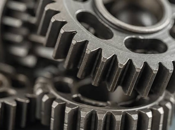
Gear tooth profile design is a fundamental aspect of mechanical engineering, particularly within the context of industrial applications. Gears are crucial components that facilitate the transfer of motion and torque between machinery, impacting performance and efficiency. The configuration of gear teeth, known as the tooth profile, plays a vital role in determining a gear's effectiveness. Optimal tooth profiles contribute to the smooth movement of gears, which is essential in a wide range of mechanical systems.
The design of gear tooth profiles directly affects parameters such as load-bearing capacity, wear resistance, and noise levels during operation. A well-designed tooth profile promotes optimal meshing with its counterpart, minimizing the potential for mechanical failures. In contrast, inadequately designed tooth profiles can lead to increased friction, excessive heat generation, and premature wear, ultimately reducing the lifespan of gear assemblies.
In industrial settings, where gears are subjected to rigorous conditions and high operational demands, the importance of precise tooth profile design cannot be overstated. The implementation of advanced design principles allows engineers to enhance gear performance by addressing issues such as load distribution and alignment. Innovative design techniques, including the integration of computer-aided design (CAD) and simulations, enable the refinement of tooth profiles to meet specific functional requirements.
Moreover, effective gear tooth designs can lead to improved noise reduction, an increasingly important aspect in many industrial applications. Efficiently designed gear profiles not only optimize performance but also ensure quieter operation, contributing to better work environments and diminished noise pollution. The careful consideration of these factors underlines the significance of gear tooth profile design in the broader scope of mechanical engineering.
Fundamentals of Involute Curves
The involute curve is a critical geometric shape employed in the design of gear teeth. To understand the significance of this profile, one must first explore its mathematical foundation. An involute can be generated by unwinding a taut string from a circle. The endpoint of the string traces the involute path as it unravels, leading to a curve that maintains a constant link to the base circle of the gear. This method of generation highlights the involute's unique properties, making it an ideal choice for gear tooth profile design.
The primary advantage of the involute profile lies in its ability to provide smooth and consistent motion transmission between interlocking gears. When two gears mate, the point of contact shifts along the involute curve, ensuring that the angular velocity remains constant. This property is crucial for achieving precise synchronization in mechanical systems. Moreover, the involute curve's geometry ensures that a slight misalignment between gears does not significantly affect performance, thereby enhancing the operational reliability of gear systems.
Involute profiles also simplify the manufacturing process. As gears are fabricated using hobbing or milling techniques, the direct generation of involute curves allows for efficient production and precise contouring. This efficiency is particularly beneficial in large-scale industrial applications, where dimensional accuracy and minimized production time are paramount. Additionally, the adaptability of involute curves allows for various modifications to enhance gear performance, such as altering tooth depth or adding profiles that accommodate specific load requirements.
In summary, the mathematical principles and geometric characteristics of involute curves form the backbone of effective gear tooth design. Their unique ability to facilitate consistent motion transmission, alongside manufacturing benefits, underscores their prevalence in the engineering of industrial gear systems.
Pressure Angle Selection: A Comprehensive Analysis
The pressure angle in gear design is a critical parameter that significantly influences the performance characteristics of gears in industrial applications. The three commonly used pressure angles are 14.5°, 20°, and 25°, each offering distinct advantages and disadvantages. A thorough understanding of these pressure angles can guide engineers in optimizing gear tooth profiles to meet specific operational requirements.
Starting with the 14.5° pressure angle, this design promotes smoother engagement of gear teeth, resulting in lower noise and vibrations during operation. It delivers a higher contact ratio, which enhances load-bearing capabilities. However, its narrow tooth profile is more susceptible to wear and can lead to higher stresses under extreme load conditions.
Conversely, the 20° pressure angle is the most widely used and serves as a balance between performance and strength. It exhibits a favorable trade-off by providing enhanced load-carrying capacity and durability while maintaining reasonable noise levels. Many industrial applications favor this angle due to its overall versatility and compatibility with standard gear systems.
The 25° pressure angle, on the other hand, increases the tooth thickness and root strength, thus improving the transmission of higher loads without failure. This selection is particularly advantageous in heavy-duty applications where strength and power transmission efficiency are paramount. However, the increased pressure angle can lead to greater noise and vibrations, making it less suitable for applications requiring quiet operation.
Each pressure angle has implications on gear design that must be evaluated with respect to the intended application. Factors such as strength, contact ratio, and load-bearing capabilities should guide the selection process to ensure optimal performance in various industrial environments. Emphasizing the trade-offs related to each option is key to making informed design choices that align with operational demands.
Choosing the Right Module and Pitch
In gear design, selecting the appropriate module and pitch is a critical aspect that directly influences the performance and efficiency of the gearing system. The module, defined as the ratio of the pitch diameter to the number of teeth, serves as a fundamental parameter that determines the size of the gear. A larger module corresponds to a larger gear with greater tooth volume, potentially leading to enhanced load capacity and strength. However, this increase in size may also result in greater weight and increased material requirements, which can affect cost-effectiveness in various industrial applications.
On the other hand, the pitch, which defines the distance between corresponding points on adjacent teeth, plays an equally important role in gear functionality. When choosing the pitch, it is essential to consider the operational conditions and the nature of the load the gear will encounter. For instance, gears designed for high-speed applications require careful pitch selection to minimize the adverse effects of backlash and ensure smooth operation. Conversely, gears intended for heavy-duty applications often benefit from a smaller pitch that allows for better tooth engagement and load distribution.
Examples of differing module sizes in practical applications illustrate the significance of these choices. In automotive applications, where compactness and lightweight are essential, smaller modules are typically favored. In contrast, industrial machinery operating under high loads may require larger modules to withstand stress and effectively transmit torque. Mechanical engineers must thoroughly analyze these factors, balancing performance, durability, and manufacturing considerations to optimize gear profiles. This critical decision-making process is instrumental in enhancing the functionality of geared systems while ensuring reliability across diverse applications.
Tooth Modification Techniques for Enhanced Performance
Tooth modification techniques are essential in optimizing gear tooth profiles, enhancing their efficiency and longevity in industrial applications. These modifications address various operational challenges such as wear, stress concentrations, and noise generation. Three notable tooth modification techniques include tip relief, root fillet optimization, and lead crowning.
Tip relief, also known as tip modification, involves reducing the profile at the gear tooth tip. This technique serves multiple purposes, primarily aimed at lowering the stress concentrations that occur during engagement. By providing a smoother transition from the tip to the tooth flank, tip relief minimizes the impact loads, thereby enhancing the gear’s operational smoothness and reducing the likelihood of tooth breakage. This technique is particularly beneficial in systems with high load fluctuations.
Root fillet optimization addresses the curvature at the base of the gear tooth. The root fillet is crucial as it serves as a stress concentrator. By optimizing the fillet radius, engineers can effectively distribute the loads more evenly across the tooth base, which diminishes the risk of premature failure or fatigue. This modification not only extends gear life but also promotes quieter operation, which is a significant factor in various industrial applications.
Lead crowning, contrastingly, is a technique focused on the axial direction of the gear teeth. Crowned leads allow for better alignment during operation by accommodating inevitable misalignments that can arise in practical settings. This modification ensures a more uniform load distribution across the tooth surface, leading to enhanced performance and longevity. In addition to improving alignment, lead crowning also contributes to noise reduction, generating a smoother operational experience.
Incorporating these tooth modification techniques is imperative in gear design. By implementing tip relief, root fillet optimization, and lead crowning, manufacturers can dramatically improve gear performance, reduce wear, and extend service life, ultimately leading to more efficient industrial applications.
Profile Corrections: Reducing Noise and Extending Gear Life
Profile corrections in gear design play a vital role in enhancing the performance and operational efficiency of gears used in various industrial applications. By implementing strategic modifications to the tooth profile, manufacturers can achieve a significant reduction in noise levels and extend the operational lifespan of gears when subjected to load. Commonly, profile corrections are categorized into three primary types: undercut, tip relief, and root fillet modifications.
Undercut corrections involve altering the tooth profile's base area, which can reduce stress concentrations and improve load distribution throughout the gear mesh. This adjustment can dramatically decrease the noise generated during operation, yielding smoother performance. Tip relief, on the other hand, entails reducing the tip of the gear tooth, allowing for optimal contact with the mating gear during engagement. This approach not only diminishes operational noise but also mitigates the effects of misalignment and backlash, leading to longer gear life.
Additionally, root fillet modifications promote better stress distribution at the base of the gear tooth, which is crucial in high-load applications. By incorporating these profile corrections, gears can operate more efficiently, minimizing wear and tear while ensuring a quieter performance. For instance, in automotive or heavy machinery applications where gears are subjected to rotational forces and vibrations, implementing profile corrections has proven to significantly enhance reliability and longevity.
Real-world applications reflect the efficacy of these strategies. In one case, an industrial application for a wind turbine gearbox employed tip relief corrections, which resulted in noise reduction of up to 30%, simultaneously increasing the expected service life of the gears by over 40%. Such examples illustrate the critical importance of profile corrections in optimizing gear performance, thus underscoring their value in extended operational contexts.
Balancing Standard and Non-Standard Profile Designs
In the realm of gear tooth profile design, an essential consideration is the balance between standard and non-standard profile designs. Standardized gear profiles, such as involute spur gears or helical gears, are widely utilized due to their established manufacturing processes, ease of design, and widespread availability. These profiles offer predictable performance and are suitable for a variety of applications, making them a go-to choice for many industries. However, as the demands of modern engineering evolve, the advantages of non-standard profiles can become evident in specific scenarios.
Non-standard gear profiles are often tailored to meet unique operational requirements that standard profiles may not adequately address. Custom gears can be designed to optimize specific parameters such as load distribution, durability, and efficiency in particular environments or applications. For instance, when dealing with conveyor drives, optimizing spur gear profiles can yield significant improvements in performance. The ability to fine-tune parameters such as tooth shape and size helps mitigate wear and tear, particularly when the gear experiences variable load conditions.
Moreover, high-speed applications frequently necessitate the use of helical gear profiles, where custom designs can dramatically affect efficiency, noise levels, and load capacity. By adjusting factors such as helix angle and tooth form, engineers can create bespoke helical gears that facilitate smoother operation at elevated speeds, minimizing vibrations that could compromise system integrity.
In conclusion, while standard gear profiles provide dependable performance for a multitude of contexts, non-standard designs can offer superior benefits when tailored to specific application demands. Companies with long-standing expertise in custom gear design stand to gain a competitive edge through optimized gear profiles that enhance performance, reliability, and overall system efficiency.
Quality
Expert gear manufacturing with 20 years experience.
GET IN TOUCH
Tel:+86-571 88065675 | +86-571 88842852
E-mail:oceanindustry@vip.163.com
Fax:+86-571 88844378
Address:4th Floor, Block 2, Qianjiang Century Industrial Park, 2327 Hongning Road,Ningwei Town,Hangzhou, China
© 2005. All rights reserved.