
Spiral Bevel Gears Explained: Design, Operation, and Applications

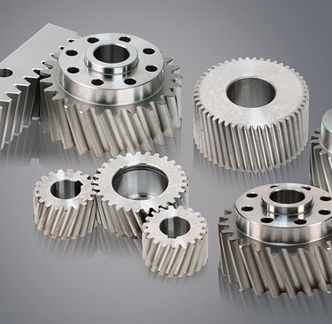
A spiral bevel gear is a conical gear with teeth that curve across its face at an angle. It is designed to transfer rotary motion and power between intersecting shafts, most commonly shafts arranged at 90 degrees. This configuration allows a drive to change the direction of rotation within a compact space, making spiral bevel gears useful in machinery where shafts cannot remain parallel. The term “sipral bevel gear” is usually a misspelling of “spiral bevel gear”; the standard name describes the curved tooth form that distinguishes this gear from other bevel designs.
Bevel gears are defined by their cone-shaped pitch surfaces, the theoretical surfaces along which mating gears roll together. Their axes intersect rather than run parallel, unlike the parallel-shaft arrangement typically served by spur or helical gears. The teeth of a bevel gear may be straight, spiral, or arranged in other specialized forms. In a spiral bevel gear, the teeth follow a curved path across the conical surface and meet their mating teeth progressively, rather than engaging across the full tooth width at once. This curved geometry is the defining feature of the spiral type, not simply the fact that the gear is angled.
The shape and orientation of the teeth influence how a gear set engages, while the conical form enables motion transfer between intersecting axes. Spiral bevel gears are manufactured and paired with attention to tooth geometry and alignment, because the contacting surfaces must mesh correctly under load. They are commonly selected for applications that need a smooth change in shaft direction and reliable transmission of torque, including vehicle differentials, industrial drives, and power-transmission equipment. Although a right-angle arrangement is especially common, the shafts need not always intersect at exactly 90 degrees; the design can accommodate other shaft angles when the gear set is specified accordingly. Understanding these basics helps distinguish a spiral bevel gear from a generic bevel gear: all bevel gears use cone-shaped pitch surfaces, but only the spiral form has curved, angled teeth. This combination of intersecting-shaft layout and curved teeth defines the component and explains its role in mechanical systems.
A spiral bevel gear transfers motion through contact between two conical gears whose shafts intersect, most commonly at a right angle. One gear is often a small driving pinion, which engages a larger mating gear. As the pinion rotates, its curved, angled teeth push against the teeth of the driven gear, changing the direction of the rotating power while carrying torque from one shaft to the other. The spiral tooth form allows engagement to begin gradually and progress across the tooth face, rather than occurring suddenly along a straight line.
The number of teeth on each gear determines the pair’s speed ratio. When a small pinion drives a larger gear, the larger gear generally makes fewer rotations for each turn of the pinion. This reduction in output speed can provide greater output torque, which is useful when equipment needs controlled movement or additional turning force. The actual torque available depends on the input, gear geometry, materials, lubrication, and operating conditions; friction and other mechanical losses mean that the output is not perfectly efficient. Reversing which gear drives the pair also changes the relationship between input and output speed and torque.
Reliable operation depends on more than tooth count. The shaft angle and the gears’ mounting distance must match the design so that the teeth meet in the intended position. Accurate alignment helps distribute the load across the contact area, reducing concentrated stress, vibration, noise, and premature wear. Tooth contact should be checked during assembly because an incorrect pattern can indicate that the gears are positioned poorly or that components are not seated correctly. Appropriate bearing support and adjustment help maintain alignment as forces act on the shafts. When these factors are controlled, a spiral bevel gear set can transmit power smoothly and consistently, even under demanding operating loads. Its ability to redirect rotation while adapting speed and torque makes it suitable for machinery with intersecting shafts, provided the gear pair is installed and maintained according to its specifications.
Spiral bevel gears transfer rotation between shafts whose axes meet, commonly at right angles. Their teeth are curved across the face rather than running straight from the inner to the outer edge. This curvature lets each tooth enter mesh progressively: contact begins near one end and spreads across the tooth as the gears turn. The gradual engagement distributes load over time and reduces abrupt impact, which can make operation smoother and quieter than a comparable straight bevel gear set. Curved geometry can also support higher speeds and loads when the gears are designed and installed appropriately.
The spiral angle describes the direction and degree of tooth curvature relative to the gear axis. It influences how gradually teeth engage, the forces produced during operation, and the gear set’s running characteristics. A larger or smaller angle is selected according to requirements such as speed, load, noise, and available space; it is not a measure of the gear’s overall cone shape. Bevel teeth are arranged on a pitch cone, an imaginary surface that represents the rolling action between mating gears. The cones meet at a common apex when the shafts intersect, helping define the tooth proportions and the gear pair’s alignment.
Tooth contact is important because a well-adjusted pair should share load across an appropriate area of the tooth surfaces. Poor alignment, incorrect mounting distance, or unsuitable adjustment can concentrate contact near an edge, increasing wear and noise. Straight bevel gears use teeth that run more directly across the face, making their geometry comparatively simple, though their engagement is generally less gradual. Hypoid gears are related to spiral bevel gears but have a key distinction: their shaft axes are offset and do not intersect. This offset can allow a lower driveshaft position in vehicle applications and changes the tooth geometry and sliding action. Hypoid gears therefore require designs and lubrication suited to their operating conditions; they should not be treated simply as ordinary spiral bevel gears.
Spiral bevel gears offer several operational advantages over straight bevel designs, particularly when smoothness and noise control are priorities. Their curved teeth engage progressively rather than making contact across the tooth face all at once. This gradual engagement can reduce impact, vibration, and the sharp meshing noise associated with abrupt contact. The result is often quieter, more refined power transmission, especially at moderate or high speeds. Their geometry also allows compact arrangements that redirect rotation between intersecting shafts, making them useful where space is limited. These qualities can support consistent operation in automotive differentials, machine tools, and industrial drive systems.
When correctly engineered and installed, spiral bevel gears can transmit substantial loads while maintaining dependable contact between mating teeth. Load capacity depends on tooth geometry, face width, material strength, heat treatment, and the stiffness of shafts and supporting bearings. Their curved tooth form does not automatically guarantee greater capacity; sizing and the surrounding assembly must suit the torque, duty cycle, and shock loads. Precision mounting is especially important because small errors in shaft position or gear setting can shift the contact pattern, concentrate stress, and accelerate wear. Careful setup therefore helps preserve both strength and the smooth running characteristics expected from the design.
These benefits involve trade-offs. Spiral tooth forms are more demanding to manufacture, and inspection of tooth geometry and contact patterns requires suitable equipment and expertise. The sliding component of tooth contact can generate friction and heat, so efficiency may be lower than expected if the mesh is poorly lubricated or operated outside its intended range. Lubricant selection and supply, surface finish, and operating temperature all influence performance. Material choice and heat treatment affect resistance to fatigue and wear, while speed and load determine thermal and mechanical demands. Consequently, real-world efficiency and service life depend on the complete gear system, not tooth shape alone.
Manufacturing spiral bevel gears begins with selecting geometry suited to the required speed, torque, space, and direction of power transfer. Designers establish tooth count, spiral angle, pressure angle, mounting distances, and other dimensions so the two gears mesh correctly. Because the pinion and larger gear operate as a pair, their geometry must be coordinated rather than designed independently. Material selection also depends on service conditions: alloy steels are common where high loads and wear resistance are priorities, while other steels, nonferrous metals, or engineered materials may be appropriate when weight, corrosion resistance, noise, or operating environment matters.
Tooth surfaces are produced by cutting or generating methods, using specialized equipment and tooling to create the required curved, angled teeth. The manufacturing route varies with gear design, production volume, and accuracy requirements. Where the application calls for improved strength or durability, gears may undergo heat treatment after machining. This can increase hardness and resistance to fatigue, but it may also cause dimensional changes, so subsequent operations may be needed to restore accuracy. Finishing processes, including grinding or lapping, refine tooth surfaces and help establish smooth engagement. Lapping is often performed with the gears running together, allowing a matched pair to develop a suitable contact pattern.
Quality checks verify that the gears meet both dimensional specifications and operating requirements. Inspection may cover tooth spacing and profile accuracy, key dimensions, hardness, and surface condition. Assemblers also check backlash—the clearance between meshing teeth—and inspect the contact pattern, often using marking compound to reveal where the teeth touch under controlled conditions. The pattern can indicate whether alignment and adjustment are appropriate before the gearset enters service. Results depend on correct mounting as well as manufacturing accuracy, so inspection should consider the assembled pair. Since finishing and lapping can make the members a matched set, they should generally remain paired and be installed in their designated relationship. Keeping identification and inspection records helps preserve that pairing and supports reliable maintenance.
Spiral bevel gears are used when a drive must redirect rotation between intersecting shafts, commonly through a right angle. Their curved teeth engage progressively, which can support smoother, quieter operation than straight bevel teeth in comparable conditions. This makes them useful in systems that need compact power transmission, though selection depends on the full design rather than on shaft angle alone.
Automotive differentials are a familiar application: bevel gearing transfers torque from the driveshaft to the axle shafts, allowing power to reach the wheels while accommodating their different speeds during turns. Spiral bevel gears also appear in vehicle drivetrains and other power-transfer assemblies where the layout calls for a change in direction. In industrial equipment, they can be incorporated into gearboxes, mixers, conveyors, and related machinery to connect a motor or input shaft to a perpendicular output.
Machine tools may use bevel gearing to drive components arranged across intersecting axes, while agricultural machinery can use it in equipment such as tractors and harvesting systems. Marine applications include selected propulsion and auxiliary drives, where the gear arrangement must fit the vessel’s installation and withstand its operating loads. In some aerospace mechanisms and robotics systems, spiral bevel gears provide a compact way to route motion through an angle. These are representative uses, not a guarantee that this gear type is appropriate for every machine.
The suitable gear form depends on required torque and speed, permissible noise and vibration, shaft arrangement, available space, and operating conditions such as duty cycle, lubrication, and exposure to contamination. Load direction, efficiency targets, maintenance needs, and manufacturing cost may also influence the choice. Other options, including straight bevel, hypoid, worm, or helical arrangements, may better meet particular requirements. Engineers therefore compare the transmission’s geometry and performance needs before choosing spiral bevel gears, rather than treating them as the default solution for every right-angle power transmission.
Selecting a spiral bevel gear pair begins with the demands of the application. Determine the power and torque to be transmitted, operating speed, and required gear ratio, allowing for starting loads, shock, and possible future changes. Confirm the shaft angle and any offset, since these affect gear geometry and compatibility. Assess the duty cycle, available installation space, and acceptable noise levels. Material and heat treatment should suit the expected loads, operating environment, and required service life. Lubrication is equally important: choose a gear set and lubricant that meet the equipment maker’s recommendations for load, speed, temperature, and contamination exposure.
Installation accuracy strongly influences capacity, efficiency, and service life. Follow the manufacturer’s specifications for mounting distances, fasteners, lubricant, and assembly sequence rather than relying on visual judgment alone. Set bearing preload and gear backlash to the prescribed values, using the specified measuring methods and tools. Incorrect preload can cause excess heat or premature bearing failure, while excessive or insufficient backlash can contribute to noise, impact loading, and tooth damage. Check tooth contact patterns and shaft alignment after adjustment. If the contact is uneven or outside the specified area, correct the setup before operating the equipment under load.
Regular monitoring helps identify developing problems before they cause a breakdown. Inspect lubricant condition and level, and watch for contamination, discoloration, or metal particles. Track operating temperature, noise, and vibration against normal readings; changes can indicate misalignment, inadequate lubrication, excessive loading, or wear. Investigate abnormal trends promptly instead of treating them as routine operating variation. During scheduled service, inspect accessible teeth, bearings, seals, and mounting components for damage or looseness. When a gear pair is worn or damaged, follow the equipment maker’s guidance on repair or replacement. Spiral bevel gears are often manufactured and matched as a pair, so replacing only one member may produce poor contact, excess noise, or accelerated wear. Use compatible components and repeat the prescribed alignment and contact checks before returning the equipment to service.
Quality
Expert gear manufacturing with 20 years experience.
GET IN TOUCH
Tel:+86-571 88065675 | +86-571 88842852
E-mail:oceanindustry@vip.163.com
Fax:+86-571 88844378
Address:4th Floor, Block 2, Qianjiang Century Industrial Park, 2327 Hongning Road,Ningwei Town,Hangzhou, China
© 2005. All rights reserved.